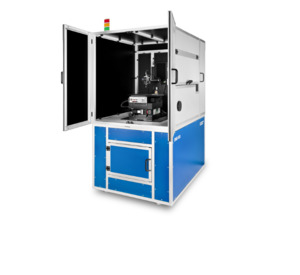
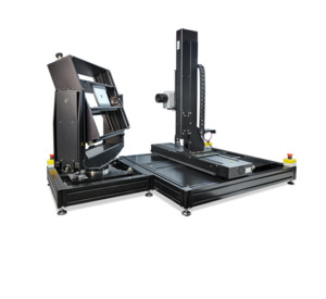
DMS 904 Fully automated 7-axis goniometer for very long, curved displays
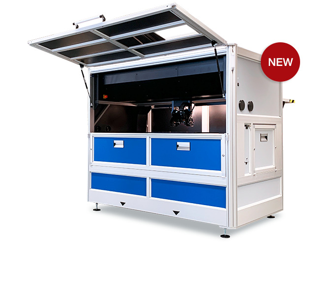


Maximum flexibility for quality control and lab analysis
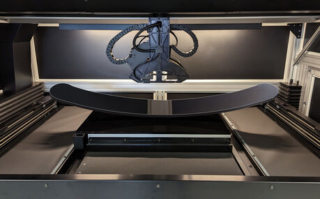
The DMS 904 was developed for photometric and colorimetric analysis of very long, curved displays. The measuring system is based on a 7-axis goniometer. Its additional X-axis ensures maximum freedom of movement, enabling the measurement of all display types for modern automotive cockpits and determination of their viewing angle-dependent properties.
The DMS 904 is used in both quality control and research & development. Its spacious interior is designed for specimens up to a size of 1800 mm x 1200 mm (about 85”).
Product details:
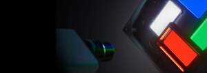
- Characterization of emissive, transmissive, reflective and transflective displays
- 7 motorized axes for visual direction scan and flat scanning of samples, without rotation of the specimen during measurement
- Examination of all photometric and colorimetric properties as a function of viewing direction, electrical control, time and temperature
- Optional temperature control chamber for measurements on long, curved displays (XZ scan)
- Optional array spectrometer for precise radiometric and photometric measurements
- Optional directional lighting for the evaluation of reflective properties (e.g. BRDF). Diffuse light source with adjustable diameter (1°–15°) for the simulation of ambient lighting
- Motorized microscope aperture and integrated viewfinder camera
- Extensive range of accessories for testing under varying lighting and temperature conditions
DMS accessories
- Combined light meters: microscope, photometer, spectrometer
- Temperature control chamber HCS-7 (-40 °C to +105 °C) for lateral moving measuring heads
- Light sources and illumination units
- Unit for sample control
DMS software
- Software packages DMSControl (control) and ViPer (preparation and evaluation of measurement results)