LumiTop M150 High-resolution imaging colorimeter for microLED characterization
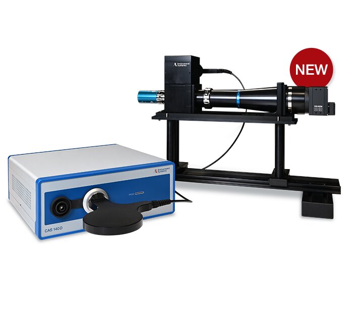



Spectrally referenced imaging for microLED display, wafer, and optical interconnect testing
The LumiTop M150 combines a 151-megapixel RGB camera, microscope optics, and a simultaneously acquired CAS140D reference spectrum for high-resolution, spatially resolved measurements. Designed for microLED displays, microdisplays, and wafer-level testing, it supports the evaluation of individual emitters for development, inspection, and quality control. Its measurement capabilities also open up opportunities for emerging applications such as optical interconnects (CPO/NPO).
Analyze individual emitters across large arrays
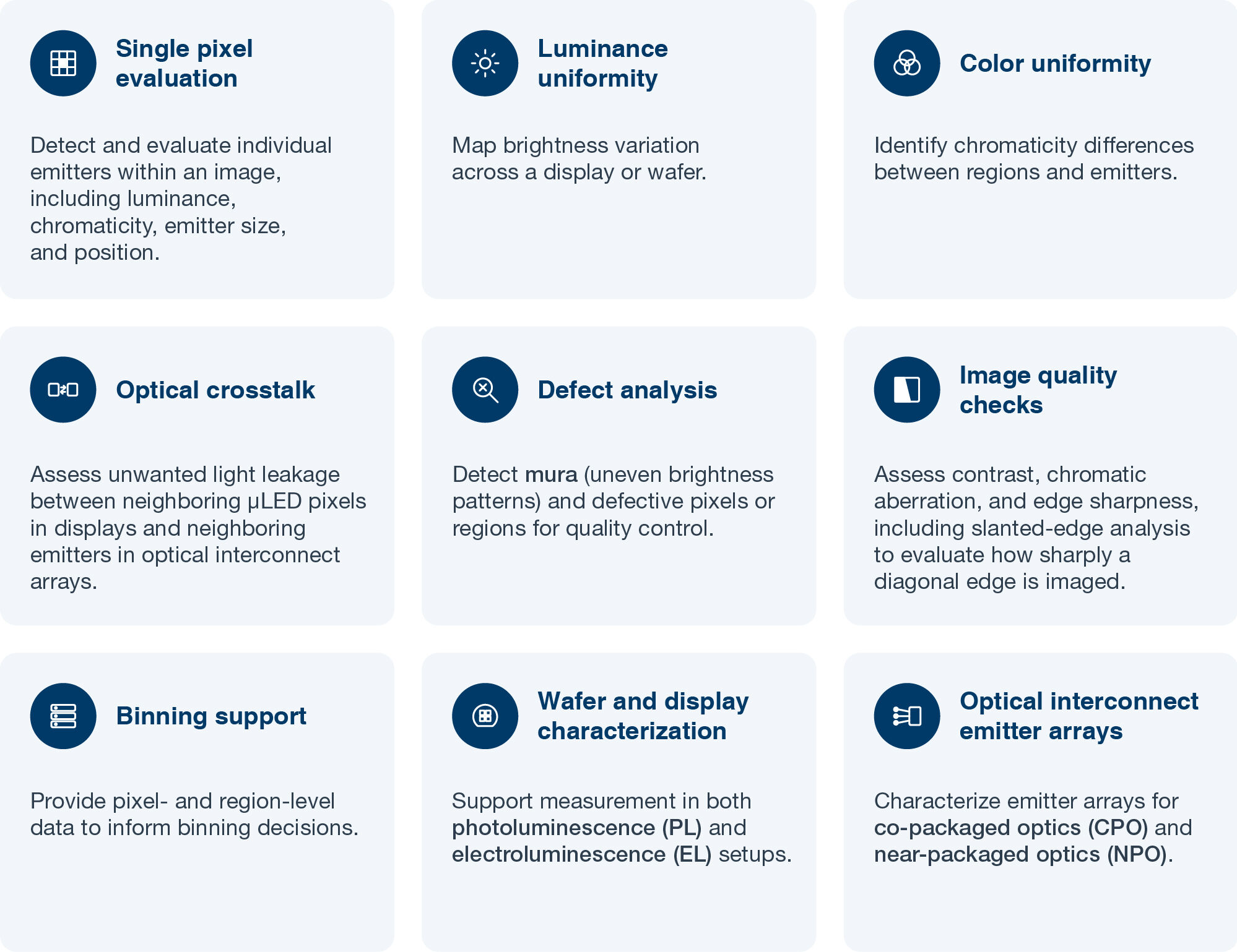
A 151 MP RGB CMOS sensor and interchangeable microscope optics resolve fine emitter structures, enabling analysis of emitter position and size, luminance, chromaticity, and spatial uniformity.
Acquire an image and spectral reference together
The CAS140D spectroradiometer records a reference spectrum during image acquisition. Spectral referencing supports colorimetric evaluation of narrowband microLED emission and complements the detailed spatial information in the camera image.
Adapt measurements to your device
Microscope magnifications provide different fields of view and spatial sampling. LiveCal and MyCal offer calibration options for varying measurement tasks, subject to the selected configuration.
LumiTop M150 – Product details
- 151 MP RGB CMOS sensor (14,192 × 10,640 pixels)
- Microscope optics: 4.5×, 11.25× and 18× magnification options
- Simultaneous RGB image and CAS140D spectral reference acquisition
- Pixel-level luminance and chromaticity analysis; emitter size and position evaluation
- LumiSuite analysis functions, including uniformity and defect evaluation
- Available as a standalone imaging colorimeter or for integration into DMS goniometer systems
Emerging application: optical interconnects
Co-packaged optics (CPO) and near-packaged optics (NPO) bring optical emitters and their electronics closer to the processor, supporting higher-bandwidth data transfer. As these architectures move toward production, teams need to verify the optical output, uniformity, and spectral behavior of emitter arrays consistently and at speed.
The LumiTop M150 supports this work with one-shot, spatially resolved imaging of emitter arrays, combined with spectrally referenced luminance and color data. Development teams can use it to characterize emitters at the device level, and production teams can use it to check array uniformity against defined limits. Suitability depends on the emitter wavelength and array format, and our team can advise on your specific setup.
Typical testing and inspection use cases
Value for development and production
For development and research teams
The LumiTop M150 gives research teams a detailed view of how emitters behave across an entire array. Engineers can compare process variations and build reference data for new designs. Spatial imaging and the reference spectrum are recorded together, supporting the evaluation of emitter arrays.
For production and quality control
In production, the LumiTop M150 supports fast, repeatable measurements for array inspection. Application-specific calibration and measurement limits can support automated pass/fail decisions, depending on the configured software and production setup. Results can be used for further analysis and reporting.
Designed for flexible integration
The LumiTop M150 can be used as a standalone imaging colorimeter or integrated into automated measurement systems.
For comprehensive testing applications, the LumiTop M150 can be incorporated into a DMS Goniometer, combining high-resolution imaging with precise sample positioning and automated measurement workflows. Python scripts and the LumiSuite SDK support customized automation and integration into existing processes.
LumiTop M150 – Technical data
Microscope magnification options
Ready to see how the LumiTop M150 fits your microLED development, optical interconnect, or production line? Contact our team to discuss your measurement requirements, arrange a demonstration, or request a sample measurement.
What makes microLED testing different from LCD and OLED testing?
LCD panels use a backlight and color filters, so the light is largely uniform across the panel. OLED and microLED displays generate light at each pixel, which makes pixel-level variation a key measurement concern. MicroLED pixels can be much smaller than OLED pixels and have narrow emission spectra, so they require higher spatial resolution and spectrally referenced measurement to produce reliable results.
Why does spectral referencing matter for microLED measurement?
MicroLED technology is still less mature than established display technologies, and its emitters show larger spectral variations, including pixel-level wavelength differences and peak shifts of typically 5 nm or more. Small shifts in emission peak wavelength between emitters can cause color errors that conventional colorimeters do not correct. The M150 records a reference spectrum alongside each image, so it takes spectral variations into account, either automatically (LiveCal) or by user input (MyCal). As a result, color values can be corrected for these variations.
Can the LumiTop M150 measure both displays and wafers?
Yes. The system supports display-level testing, including microdisplays for AR/VR headsets and smart glasses, and wafer-level measurement in photoluminescence (PL) and electroluminescence (EL) setups.
Which software is used to analyze the data?
LumiSuite provides the graphical interface and analysis tools, including single pixel evaluation, uniformity, and defect analysis. The LumiSuite SDK supports custom integration, and DMSOcto is used for operation in the full tester configuration.
Is the LumiTop M150 suitable for optical interconnect applications?
This depends on the emitter wavelength and array format. Please contact our team to discuss your specific application.


